Like many homeowners our central ducted heat pump gave up the ghost. We installed it new around 20 years ago and had to decide what to do next. So I called the same company that installed it 20 years ago and when I got the estimate to simply replace the existing unit with a new one I almost had a coronary. It turns out that the three largest purchases you will make in your lifetime are a home, a car and then apparently an HVAC system.
I looked up online the cost of the units and then did the raw math on the hourly rate the HVAC installers were going to be charging me. The numbers were between $600-$1800 per hour. Yes I understand they have overhead and are running a business so they need turn a profit. At the same time I also understand that there are many people like myself that simply cannot afford or do not want to afford that kind of mark-up, and yet we still need heating and cooling so I set out to find a different solution. Going on year three and couldn’t be happier with the savings and the performance of the units. Our house is cool when the outdoor temp hits 115F in summer and warm in the winter when temps drop into the teens with a very reasonable power bill.
Is it Legal to install your own?
Before starting this project you will want to call your local building department and ask if you can pull mechanical and electrical permits in your jurisdiction, you do need to be the homeowner for this to even have a chance of being permitted. You do want to do this if you carry home owners insurance as unpermitted work can void your insurance. Get it permitted and inspected!
EPA certification: You are required to have EPA certification to handle or work on anything that contains refrigerant. Luckily if you can get by with a mini split that uses less than 5lbs of refrigerant most 24k BTU units and down do, you only need a type 1 608 Certification. You can obtain one online by taking an open book, untimed, multiple choice test and paying the required $25 dollar fee. So for $25 and a bit of time researching the answers you can become a certified EPA HVAC technician. Certification is for life and there is the only the one time fee. They send you a laminated EPA certification card with a unique federal ID number, you can use this card to legally purchase refrigerant if you need to in the future.
Step One: Decide How many tons of heating cooling you need.
If you have an existing system you can find the tons on it, if it met your needs for heating and cooling then you can just replace with the same total tonnage. If you had a 4 ton system (48k BTU) then you could install 4 1 ton (12k BTU) minisplits to replace your existing system. I highly recommend doing as many single head units as possible as opposed to multi head mini splits (multi head units have multiple indoor units all tied to single outdoor condenser unit) single head units have one indoor unit paired with one outdoor unit. If you do single head units: the install is easier, the units are more efficient in terms of power usage, you have complete independent control of each space (multi head units must all operate on the same setting heat/cool) and you have redundancy in your heating/cooling system. Why all HVAC systems are not designed with redundancy is beyond my comprehension. The only down side to multiple single head units is that each requires it’s own dedicated two pole breaker in your electrical panel and you will have multiple outdoor condensers.
Step Two: Decide where you will be placing the indoor and outdoor units.
So placing the units is very important both from an ease of install point of view and in terms of how effective the units will be at keeping your house warm or cool. The indoor units work best placed where they can take in air from the top of the unit, usually at least 6 inches from the ceiling (were hot air rises) and aimed the long ways in a room. Think refrigeration semi trailer, they have one unit at the front of the trailer that services the whole entire space. Same exact concept. Open floor plans work better than small tiny rooms with doors. Do make certain this is a viable option, if you have a large home that is sectioned off then minisplits may not be your best option. If you already have good ducting you can go with an inverter based outdoor unit paired with an indoor air handler there are DIY products for that as well, but that is another article. Ideally you want the indoor units mounted on the interior of an outside wall as the copper lines must go through the wall and connect to the outdoor unit. You want to keep the distance from the hole in the wall to the outdoor unit under 30′ if possible, ideally in the 10′-15′ range for ease of installation.
Step Three: Order the Correct Units
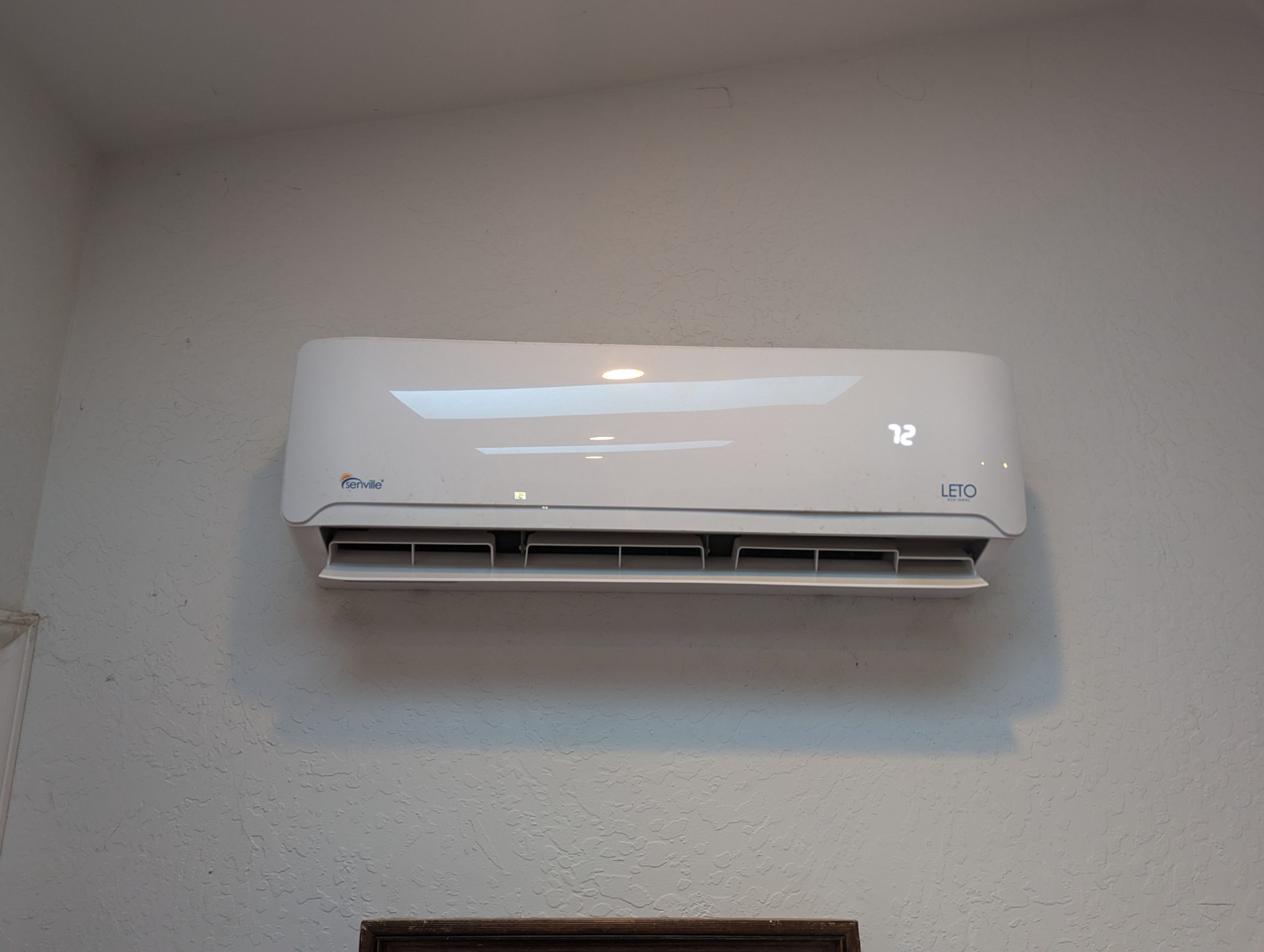
The best time to order them is spring and early fall as this is the slow time and the units usually will be on sale, especially in the spring. I am going to recommend one particular brand although any Midea (rebadged units) will all be roughly the same. I have had very good luck dealing with Senville out of Canada. Are the Mitsubishi units better? Yes they are, will they last any longer than the Senville units? Probably not. These new mini splits have more in common with computers than they do with the HVAC units that lasted 20 years in the past. As such they are disposable items that have a useful service life of around 12-15 years.. although if installed properly and maintained they can still last 20 years but as the technology continues to improve and the efficiency along with it, just like computers whatever you buy today will likely be outdated and need to be replaced within the next 10 years. So go cheap but reliable is my advice. For example purposes only our house is 2000 sqft and we installed 2 18k BTU units one at either end, our floor plan is very open and two of these units services the space perfectly. Our power usage dropped from 4400kwh to 2200kwh hours on average, much lower in the summer. The SEER rating tells you the efficiency of the unit in summer and the HSPF rating tells you how efficient the unit is at heating. For simplicity I am going to be covering the Senville units they have two lines the LETO and the AURA. If you live in a cold climate say zones 4-6 where you regularly have temps that drop below zero I would go with the AURA line, if you live in a temperature regions where winter lows will not get below the teens, then the LETO units are fine. The AURA line are low ambient units and hold their rated BTU’s when outdoor temps drop down all the way to -25F…. There are people in Minnesota using the AURA line as a sole source of heating besides emergency baseboards for those -30F nights…. I ordered one unit via Senvilles amazon outlet and one via Senville directly the price was the same, but Amazon shipped faster as they had a warehouse closer, it shipped from California vs the Factory direct unit that shipped from Canada. The units arrive via fed ex freight generally, they will pull up to your driveway. The 18k BTU units heaviest box was around 100lbs… not terribly difficult to move but if you are on the smaller side, have a friend there for delivery. On a side note, when I did this I was a bit skeptical that this whole thing could be done for so cheaply so I ordered one unit to see how it would go before ordering the second about 15 days after I installed the first.
Step 4: After delivery
Installing the indoor unit is about as difficult as hanging a new flat screen tv minus the cutting of a 3″ hole into the side of your house. I admit that of all the things I had to do to during install this was the one thing I dreaded the most. Measure 5 times is my advice, you only want one hole in your wall 🙂 I will list all the tools necessary for this install at the end of the article. Mount the bracket level on the wall where you want the indoor unit to go first. Make sure it is level as the drain pan must be level to drain condensate out properly, use a level. Make sure you have ample space above the unit for intake, Senville recommends at least 6″ of clearance above the unit and 6″ on either side for maintenance purposes. Once you have the bracket mounted to studs (easiest way I’ve found to find studs is use a neodymium magnet to find the drywall screws it will stick to them, and they are screwed into the studs). You can also use a stud finder.
You will need to determine which side of the unit the copper lines will go out it, if possible set it up so they will exit the unit on the right side as you face the indoor units front. This will make sure the condensate line runs straight out and down as opposed to running horizontal indoors before going out, if you run it horizontal you risk the issue of water pooling and staying inside the line and the pan and causing mold and or bad smells. You can then connect the 4 wires from the communication/power line that comes with the unit to the indoor unit, they are numbered 1,2,3 and green. The green is ground the 1,2,3 are color coded just make a note of which color you put to what number and do the exact same on the outdoor unit when you connect them later. You can test mount the indoor unit on the bracket, it just slides into place. then mark where the copper and condensate lines will be exiting through the wall, and finally after you are positive where that will be drill the hole through the wall at a slight downward angle as your condensate line will be draining through the hole to the outside and it is gravity fed, so make sure it has a slight slope to travel outside. After the hole is drilled and the sleeve inserted (that came with the unit) you can then gently bend the copper lines on the indoor unit so that they will be sticking out and ready to slide through the hole with your communication line, it does help if you have an extra set of hands to feed the copper lines and wires through the hole while you hold and then hang the unit on the bracket for the final time. Wrap the copper lines and communication wire with the vinyl tape provided with the units and tape them all together careful not to crush the condensate drain line, having positioned it on the bottom and that will make it easier to feed all three of them through the hole and ensure that any condensate that forms will travel to the outside. Ok that is it you are done working inside.
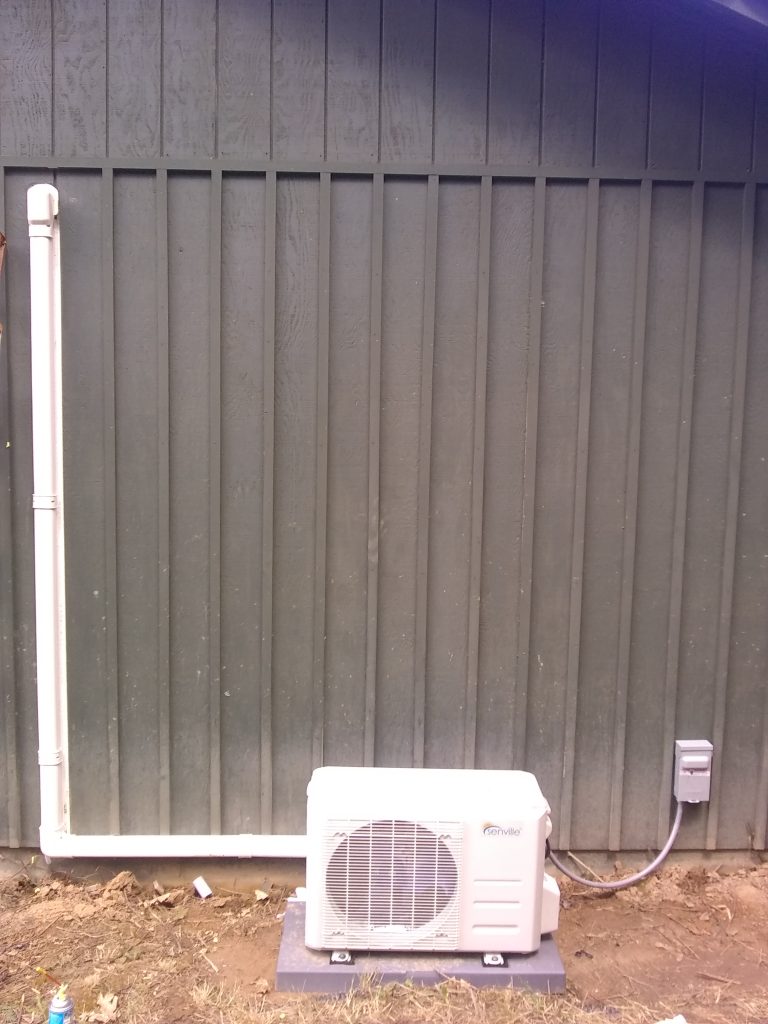
Step 5: Placing the outdoor unit:
I would order the Poly base and mount the unit on the ground if possible. If in a heavy snow zone, get the stand that will mount the unit high enough above the snow line. Ground mount is preferable as although the outdoor units in terms of decibels are very quite compared to traditional heat pumps they do vibrate as they ramp up and mounting to the wall of the house can cause vibrations to transfer to the indoor space. If mounting to brick or concrete the vibration should not be a concern but mounting to traditional wood studs and siding can transform your wall into a passive subwoofer. Avoid if possible. I would wait to do the electrical run from the breaker panel until you have finished placing the outdoor unit, if possible leave yourself some wiggle room meaning you can slide the base left or right a little if necessary when connecting the copper lines. The copper lines must be one continuous run, you can always shorten them but extending them is not possible for the DIY’er without investing in a lot more expensive tools and even then some manufacturers will void any warranty if you braze any of the lines sets (line sets are the copper lines running from the indoor unit to the outdoor unit). Tamp down and level the ground where the base will sit, it just simply sits in place and the outdoor unit is set on top of it. You can get some long screws and washers and then screw the outdoor unit to the base but do that as the very last thing you do as you may need to slide the unit left or right a bit when connecting the copper lines.
Step 6: Connecting the Copper lines and communication wires to the outdoor unit.
If you will be using line-hide(highly recommended to protect the outdoor insulation from deteriorating and because it just looks a lot more finished if you do. It is cheap and easy to install and you can paint it to match the house siding when finished if desired.) that is the plastic sleeve that the copper lines and communication wire will run through to the outdoor unit from the indoor unit. Mount the back half of the line-hide to the wall with the provided screws and then measure using a piece of string the distance from the end of the copper lines sticking out of the wall to where the outdoor unit connections will be add three feet to your measurement and then cut the copper lines to that length.
Hopefully you read this whole article before beginning and ordered a line set of the proper length. They come in various lengths, order the one you need. You want the condensate line to terminate straight down through the bottom of the vertical line hide and the copper lines will continue on to the outdoor unit. Once you have cut the ends off of the copper lines, you can technically just cut the two flares off the end that will be connecting to the outdoor unit, but I would carefully inspect the factory flares on the copper lines to ensure they are perfectly smooth without blemishes, any blemishes and I would cut off the factory flares using the copper pipe cutter than put new flares on using the tool I will list at the end of the article. Put your nuts on BEFORE you redo the flare as you can not put the nuts on after you flare it, I guarantee you will do this at least once if you do your own flares 🙂
Ok find a nice clean flat work area and you can slide the insulation off of the copper lines as you have removed the flares from one end. Now with the bare copper line, be very careful not to bend the lines. The easiest way is to unroll the copper line with the insulation on it. Gently place one foot to hold down the ends that have not been cut and then unroll the line set into a straight line on a hard flat surface. Once you remove the insulation and cut to the desired length as you measured previously, then it is time to get out the spring benders and bend the pipe by sliding the spring to where you need to bend the pipe, and gently bending it as needed. Do not kink the pipes, go slowly and do only one copper line at a time, first the 1/4 then the 1/2 inch. The copper lines should now be the right shape and length, you can can then cut the insulation to size and slide the insulation back on the copper lines.
Now you are ready to make the connections. You will need a torque wrench for this (again listed at the bottom of the article) you will connect and torque to spec the nuts on the copper lines. You will use a crescent wrench on one side and a torque wrench on the other side and torque to spec. In my case I tightened the 1/4 inch line nut to 12lbs and the 1/2 inch to 34lbs. Read the manual it will tell you the exact torque to spec. If you use Nylog (refrigerant oil) , I prefer dry fittings, do not get any of it on the threads as it will make you over torque and potentially damage the flares causing you to have to redo them. A little dab on the back side of the flare will help keep it from binding when tightening. If you are going to use a standard torque wrench with a crows foot end, make sure you only tighten with the crows foot at a 90 degree angle, if you have it straight out the torque values will be off as the torque wrench values will change if you lengthen the distance from the torque head. Once all four copper line nuts have been torqued to spec and the 3 communication plus ground wires have been connected you are finished with the hard part of this install.
Step 7: Vacuuming the system and releasing the charge.
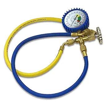
So you ordered the 1/3 hp vacuum pump with vacuum hose, a low side manifold gauge with a 5/16 end and Schrader depressor built in, a micron gauge (recommended but not 100% necessary). Unscrew the cap on the King valve, this has a Schrader bicycle type fitting and you will connect the low side manifold gauge hose to this, it should just screw on hand tight, tight but not torqued. The other end will attach to the manifold gauges connection that comes straight out of the bottom of the gauge. The yellow hose will connect the side of the gauge to the vacuum pump. Make sure the manifold gauge is open before you start vacuuming.
When you turn on the vacuum pump the gauge will drop into negative territory indicating you are creating a vacuum. Again, make sure the gauges valve is open, or you will be simply vacuuming the hose and not your units copper lines. You will let this run for at least 1 hour if you are not using a micron gauge. If you are using the micron gauge then you want to wait until the micron gauge reads less than 500 microns. When it does or one hour has passed, close the valve on the gauge and wait at least 2 hours. The gauge should remain stable and at the max negative value it started. After the two hours has passed or if using a micron gauge, it should remain below 1000 microns for the entire time. If it does not hold a vacuum, you will need to go redo your flares and connections. So it is important to leave yourself some extra copper when installing, remember you can always cut to shorten but you can not lengthen your line set.
If the vacuum held for the two hours you can then go ahead and release the refrigerant into the system by unscrewing the Allen key valves on both the copper line sets, where they connect to the outdoor unit, there are two caps, remove the caps and gently unscrew, to the left, one of the Allen key valves, do it slowly and watch the still connected manifold gauge, it should start to rise, when it gets to 30lbs, retighten the alley key, it should take very little time, under 3 seconds. This will let you do a mini pressure test of your connections, normally a professional would use a nitrogen tank and pressure test the system prior to vacuuming to ensure the system was leak free. If your system held a vacuum for 2 hours it is almost 99.999% of the time leak free. If the gauge holds the 30lbs of pressure for another hour without dropping, increasing is ok as if the temp warms up the pressure could actually increase, then you can remove your manifold gauge from the unit quickly and then go ahead and open both Allen key valves fully, they do seat at both ends so make sure you open them all the way, it should open all the way and seat at the end, not torque wrench snug open, but hand snug. Once both valves are fully open you are almost finished. If the gauge does not immediately begin moving towards positive pressure when you open the valve, then you were vacuuming your hose and not the copper lines. Besides the piece of mind of doing the mini pressure test this way, it also lets you remove the gauge with minimal release of refrigerant as you will be disconnecting with only 30psi in the system not 250psi+…
Step 8: Final Electrical and Startup of System:
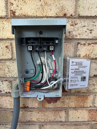
Depending what your building departments said was legal in your jurisdiction this section will vary. For me I used two existing two pole 20amp breakers in the panel and ran 12/3 gauge wire from the breaker panel along the silt base to the disconnect boxes. You need one breaker and one disconnect box per outdoor unit. The breaker size and wire gauge will be dependent on your local building codes. You also want to install a surge suppressor on the disconnect as replacing it will cheaper than replacing the main board on the outdoor unit. I used the Intermatic AG3000 on both my units. Different size units require different size breakers, the 18k LETO unit uses a 20amp breaker, check your manual to determine what size you need.
If you plan to just hire an electrician to put in the disconnect, it will still be a lot cheaper than hiring an HVAC company to handle it as they will add in fees for arranging it for you.
After the disconnect is installed there will be an electrical whip that runs the two 110v lines to the unit to give you 220v. There will be two hots and a ground, as of this date Senville does not use a common so 12/2 wire can work but I would go with 12/3 as your future unit may require a neutral. Once the power is connected, the refrigerant has been releases and settled ( give it 10 minutes at least to equalize in pressure). Then it is time to go inside and turn on the unit with the remote and take pride in knowing that you just saved yourself a LOT of money.
Epilogue:
Not counting our utility savings by installing the mini splits by DIY’ing this project my total cost savings including tools was right around 15k dollars. The first unit took me about 12 hours to install the second took about 4 hours. Total cost to install one unit was about $1500 and that included tools, so the second unit was only about $1100 including the electrical. So a redundant 3 Ton 20 seer system for right at $2600. The quotes I received for a comparable 20 SEER system were over 18k dollars.
This project is not for everyone, but for those DIY warriors that want to tackle it, It can be done and done well, hell I did it. List and links to tools and the equipment itself is below. These are the exact things I purchased, I did go with the spring benders but opted for the quality torque wrench as I knew I would end up helping family and friends do this in the future. You can pick up the drill bit and an auger at your local Home Depot as well. I do assume you have a cordless drill, standard crescent wrench, Philips screw driver and a wire stripping tool.